3次元センサを入力の一部に用いたSLAMについて、その一般的な技術分類とメカニズムについてまとめました。
前回の記事:
3次元センサを利用したSLAM (1/2)
Projected-light sensors
Projected-light sensors tend to be the most precise active depth sensing solutions but have characteristics not typically suited to SLAM applications because such sensors can be relatively slow in capturing data and are relatively susceptible to ambient light. There is a direct correlation between the working depth range and the distance between the camera and the projector. Such sensors also tend to be expensive.
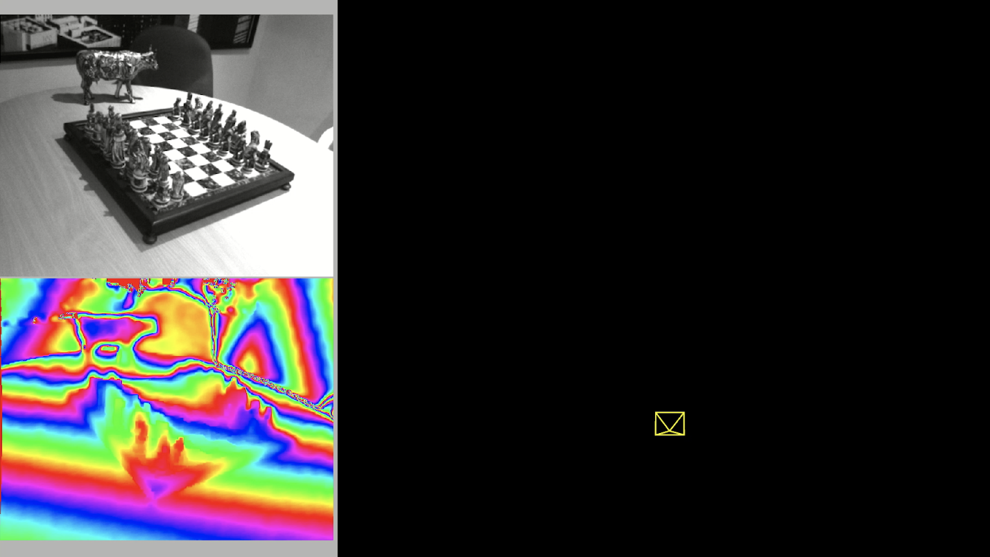
Not all projected-light sensors are subject to the limitations mentioned above. A notable exception is the first version of the Microsoft Kinect sensor, which uses structured light and has been used in publicly available SLAM datasets, such as TUM.
The following video shows Kudan SLAM working with a video sequence from TUM. The visual feed (top left) is used to extract the feature points, then the registered depth map (bottom) is read in the relevant locations to obtain the necessary depth information for constructing a 3D map of the environment and the trajectory (top right).
Matricial ToF cameras
Matricial ToF cameras typically use near-infrared LEDs to illuminate the environment, observe the illuminated scene by using the appropriate camera sensor devices, and rely on precise timings between the illumination modulation phase and sensed reflected brightness to measure the distance of the observed illuminated areas.
The advantages of ToF cameras include the relative simplicity of their designs and compactness of their form factors. The disadvantages include noise interference from sunlight and limited range due to light absorption and phase ambiguity problems. A typical example of these kinds of cameras is the second version of the Microsoft Kinect, but there are many more examples.
The following video shows Kudan SLAM working on a prototype rig that combines visual and matricial ToF camera information for mobile applications. From the SLAM point of view, this arrangement is not so different from the projected-light video shown above because both projected-light sensors and matricial ToF cameras produce the same kind of data despite using different technologies.
Please click: RGBD_KudanSLAM_custom_ToF (1)
LiDAR ToF solutions
In terms of data, LiDAR ToF solutions differ from the above cases and are the technological evolution of the simple laser rangefinders used in the 1980s for the first SLAM systems. One or more laser beams are pulsed on rotating mirrors and single-pixel detectors are used for each beam to record the reflection time for inferring the distance.
By correlating time with the angle of mirror rotation, the system can quickly generate 360° ranges and rotate in one or two directions. When rotating on a single axis, it can use more than one laser to record multiple arrays of depth ranges.
LiDAR systems tend to have longer ranges than do other depth sensing solutions. Many systems offer omnidirectional views on at least one axis, and are, in general, more resistant to outdoor illumination conditions. The disadvantages include cost, susceptibility to noise coming from particles, such as dust or rain, in the air, and complexity due to the moving mechanisms.
Another important limitation of LiDAR systems is the distortion of the resulting depth ranges caused by the motion of the system as it scans and the time taken by the mirror to complete a rotation. This effect is similar in nature to the rolling shutter effect of some camera sensors. A visual SLAM system could help solve this problem by associating the tracked feature points with the depth ranges and recovering precise motion to undistort the depth scanlines in real time.
The following video shows Kudan SLAM, which uses a Velodyne solution, running on the publicly available KITTI dataset for SLAM and visual odometry that uses a Velodyne solution. 64. Of the scanlines of depth range, 64 could be used to create depth information quickly and accurately up to 120 meters while the visual input could be used to register the moving spinning scanner as it tracks and aligns the 3D points.