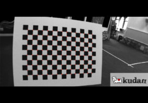
Figure 1: Calibration Chess Board
Visual SLAM is an algorithm for a moving rigid body with a camera that estimates its motion and builds a model of its surrounding environment. Visual SLAM technology is crucial in various use-cases such as autonomous driving, autonomous mobile robots, drones, augmented reality, and virtual reality.
Once you decide you'll be using Visual SLAM for a use case, you need to look for specific characteristics in the camera. We'll leave the link to an in-depth article we wrote earlier, cracking down on each characteristic at the end.
Next, once you have decided on the camera for your use case, your camera needs to be calibrated. What is calibration — you ask? The process of understanding the camera characteristics is called calibration.
Accurate calibration is of utmost priority to have an outstanding SLAM performance. You may have the best-suited camera and an excellent SLAM algorithm [1]; however, if your calibration is inaccurate, the SLAM performance will deteriorate.
However, it's easier said than done, calibration is a complex process, and various steps must be followed to calibrate a camera accurately.
In this two-part article series, first, we will introduce the entire process in a step-by-step fashion and then dive into the exact details, walking you through in-depth information in the next article.
Understanding the camera properties
To understand our camera calibration process, we must first go over the properties of a camera.
Camera properties can be classified into two classes:
- Intrinsic parameters: These are properties specific to a camera, such as a camera's sensor size, aperture, focal length of its lens, and distortion. These properties are why two cameras at the same position and orientation can produce different images.
- Extrinsic parameters: These are properties like position and orientation, which dictate how apart the cameras are and what angle they face each other.

Figure 2: Stereo camera rig
As you may have realized, intrinsic properties are all that matters for a single-camera setup, and extrinsic properties only become relevant when more than one camera is involved in the Visual SLAM system.
The calibration process: A 4-step approach
Now that we have a better understanding of the camera properties, we can define camera calibration as the process we follow to determine the intrinsic and extrinsic parameters of the cameras [2].
Not all the parameters can be measured by physically analyzing the camera, especially intrinsic parameters such as distortion. Software libraries are generally used to estimate the parameters, taking the video feed as input.
This is a standard practice in the computer vision industry, and we have left recommendations on software libraries that can be used to calibrate the camera at the end of the article.
So, thanks to software libraries, let us simplify the calibration process into four steps.
- Show a known object to a camera.
- Store the seen properties of the known object in the software.
- Move the object in front of the camera.
- Let the software calculate the intrinsic and extrinsic parameters by comparing what is seen with what is known.

Figure 3: Calibration process
The steps above would give you an overall idea of the entire approach. However, we want to provide you with all the details you'd require when you're about to calibrate.
Preparation for the calibration sequence recording
An accurate calibration starts before the process itself — during the preparation phase. Let's take a step back and understand what steps you need to perform as preparation.
- Use good lighting conditions for the entire sequence.
- Use the same camera settings (resolution, framerate, lens configuration) as in the sequences that are to be analyzed.
- Ensure that the calibration pattern is planar. To achieve this, place it on a solid planar surface that does not bend easily (Kudan uses a chess board pattern tightly put on a 1cm-thick plastic board). Ensure that the paper is not folded or scrapped. Additionally, you may flatten the paper or fix it using sticky tape.
- The calibration board needs to be as big as possible; A4 will work but isn't ideal. Measure the length of squares on the printed paper.
Further exact-walkthrough on the steps during the calibration will be covered in the second part of the series.
The parameters to look for post-calibration
Once the calibration process is finished, we have the following intrinsic parameters:
- Focal length: fx, fy
- Principal point: cx, cy
- Radial distortion: k1, k2, k3, k4, k5, k6
- Tangential distortion: p1, p2
We know that focal length is proportional to both the field of view and the width of the images. Usually, vertical and horizontal values should be similar, and in the stereo case the values between the cameras should also be close. The principal point should be around the center of the image.
Unfortunately, judging distortion parameters by looking at them is impossible because they are factors and ratios in complicated formulas.
We will have additional extrinsic parameters as follows in a stereo setup [2] but we will focus on the single-camera setup for now:
- Translation vector (3×1) from the right camera to the left camera
- Rotation matrix (3×3) to rectify cameras.
Decoding a good calibration
Aside from the ballpark considerations mentioned above, evaluating calibration quality through the numbers is challenging. Two distinct observations can be made on images after undistortion and rectification are applied:
- Straight lines in the real world should look straight in the view. Straight lines will curve close to the edges if calibration is imprecise in the distortion parameters.
- The same visual features should appear in the same scanline between left and right images. A poor stereo calibration will have a vertical disparity in the images between the same physical points.

Figure 4: Good rectified image (lines are straight and each cell is placed at same height on the left image and the right one)
Visual inspection can evaluate the conditions above in the captured images. However, measures should be repeated at different points of the images, possibly looking at different distances from the cameras.
Final words
In this article, we introduced the camera properties and understand the 4-step calibration process using software libraries, how we should prepare for the calibration and some post-calibration considerations.
Here, you can read more about choosing the best camera for your Visual SLAM use case.
For free software libraries that can be used for camera calibration, checkout OpenCV, Jean-Yves Bouguet's Camera Calibration Toolbox for Matlab, and The DLR Camera Calibration Toolbox.
If you've got more questions on your specific use cases, please feel free to reach out to us, and meanwhile, keep an eye on this space for the follow-up article on camera calibration.
References
[1] Taketomi, Takafumi & Uchiyama, Hideaki & Ikeda, Sei. (2017). Visual SLAM algorithms: a survey from 2010 to 2016. IPSJ Transactions on Computer Vision and Applications. 9. 10.1186/s41074–017–0027–2.[PDF]
[2] Qi, Wang & Li, Fu & Zhenzhong, Liu. (2010). Review on Camera Calibration. 3354–3358. 10.1109/CCDC.2010.5498574. [PDF]
[3] G. Carrera, A. Angeli and A. J. Davison, (2011). SLAM-based automatic extrinsic calibration of a multi-camera rig, IEEE International Conference on Robotics and Automation, 2011, pp. 2652–2659, DOI: 10.1109/ICRA.2011.5980294. [PDF]
■For more details, please contact us from here.